Tote - A Four Legged Robot
Hello everyone! After a few weeks of work I finally have this to show - The Tote.
The Tote is a four legged robot controlled using an Arduino Pro Mini. The original design is by Radomir Dopieralski. Twelve servo motors make up its legs. Here is how I made it.
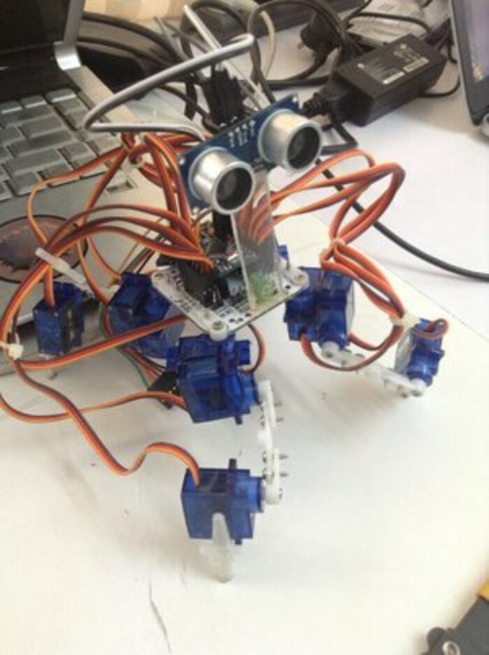
A robotic llama with its neck stretched The Tote - A quadruped robot
PARTS:
- A Tote PCB (link at the end of post)
- Arduino Pro Mini
- Several Male headers
- Jumper wires (all three kinds)
- 12 SG90 servo motors and all attachments that come with it
- FT232Rl FTDI USB To TTL Serial Converter Adapter Module for Arduino
- A pillow to scream into (this is optional)
- Ultrasonic Sensor - HC-SR04
- Mini USB cable
- Power Supply that can give out 5V 2A
- Acrylic sheet
Tools:
- Soldering Iron
- Soldering tin
- Hot Glue gun
- Dremel Tool
How to do it:
The Arduino Pro Mini acts as the brains of the robot so that’s what needs to be programmed. So after getting the Tote PCB, the first thing to do is to attach the Arduino Pro Mini onto it. The assemble of parts onto the PCB is available at this link. It works on inverse kinematics which helps in determining the exact positions of the motors. That part I had to copy the code from the original maker of the Tote because I couldn’t understand it.
A little on what the robot can do-
The robot if built properly has three programmable modes in the design I used. Mode #0 - Power Off. Mode #1 - Walk. Mode #2 - Home position. The mods #0 and #1 are self explanatory. Mode #2 gets all servos to the 0 degrees mark of the servo. It walks in an algorithm called the creep gait. The creep gait decides which legs to move forward and in what order. If the robot walks fast enough, it switches to another algorithm called the trot gait. The trot gait moves two legs at once and moves faster.
The first thing I did was attach male header pins to the PCB in the way the PCB design needed them. This process should be as precise as possible as if the pins are tilted, they wouldn’t have full contact with the PCB which may result in some parts not working.
Warning - Don’t heat up the Arduino too much while soldering it onto the PCB. If you are trying to do this project yourself keep checking if the Arduino is heating up too much.
After soldering the pins onto the PCB along with the Arduino, there needs to be a proper way to program it. Since this version of the Arduino does not have a USB output, it needs to be connected to a Serial to USB converter. This is where the FTDI Adapter module comes in. The connections are pretty simple -
GND –> GND
CTS –> GND
VCC –> VCC
TXD –> RXD
RXD –> TXD
DTR –> DTR
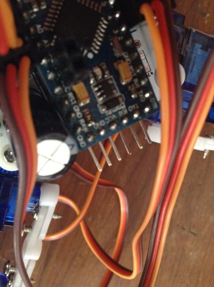
The Arduino Pro Mini’s programming pins
After all connections are secure, I used a Mini USB cable and connected it to computer through which I could upload the code to my robot.
A small mistake I kept making was leaving out the DTR connection. That particular connection acts as a reset button every time I put code into my Arduino. Without it, I have to hit the reset button every time I upload code at the very second I click “Upload”. This made it pretty hard to work without the connection. So remeber to connect the DTR. Worship the DTR. #worshipdtr
Now that the problem of programming it was solved, I needed to create the legs. There is a fully detailed guide at this link. The servos had to be screwed onto the PCB. Use the pillow if you are having too much trouble. One thing to make sure is that you don’t manually twist the servo motor. This will cause offset when the design is ready.
Each leg would look like this if you did it correctly.
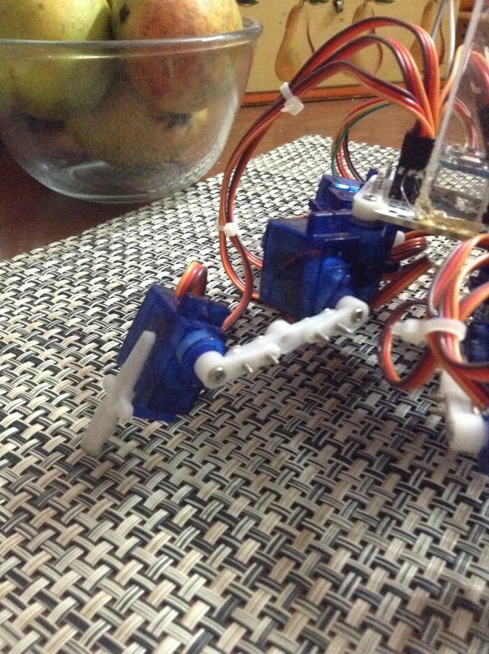
The legs - The blue cuboids are motors
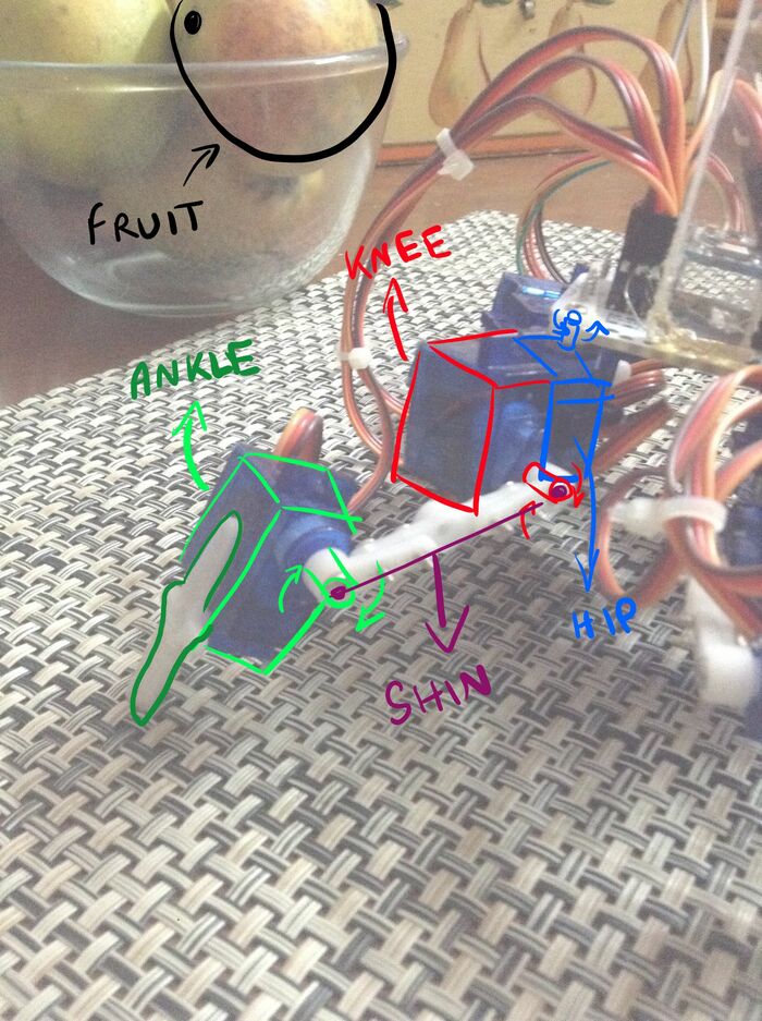
The design would look like this:
Finally, the code. The code can be downloaded from this github link: https://github.com/Aryanaut/tote-test
Use the following command to get the code onto your computer or download the .zip file.
sudo apt get update
sudo apt install git
git --version
git clone https://github.com/Aryanaut/tote-test
Now check your home directory and you should have a command “tote-test”
After some testing I wrote in the code that controls it using an ultrasonic sensor. It is available in the tote-test folder as tote-ultra.ino. Upload the code and if your connections are correct, it will work!
To connect the ultrasonic sensor, connect the Trig and Echo pins to the Arduino pins A4 and A5 respectively and the Vcc and GND pins to the Arduino pins VCC and GND. If you are using the power bank like I did, connect VCC to RAW. Do this BEFORE uploading the tote-ultra code.

My biggest problem:
My biggest problem. The one that I used the pillow to scream into was the power supply. The 9V battery that I had was too much. The rechargeable 7.4V batteries didn’t supply enough current. After several weeks my dad came up with a solution. We used a battery bank that supplied 5V 2amps which was enough for all 12 servos.
This made the “walking the dog effect”, an amazing term coined by me. It is when you build a four legged robot that continuously had power supply issues to a battery bank through a USB to serial cable causing you to walk with the robot as it moves since the cable has only a limited length. Now that I type it, it sounds way to specific for a term. But one day, mark my words, one day I will coin a term.
If you find a power supply light enough, attach it to the robot with tape or any other fixture that seems suitable.
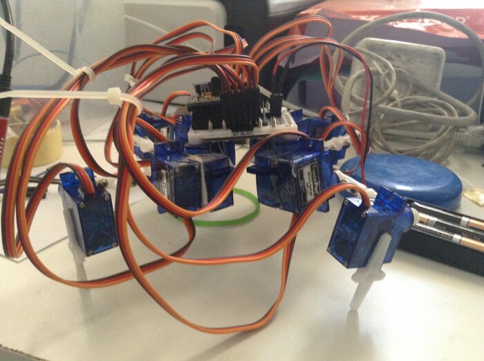
And that’s it! After screaming to pillows, melting wires, and testing, the robot is complete!

My masterpiece
Just kidding. Here’s the real one.

The wires are tied together with zip ties to avoid tangling
That’s all for now!
Live Long And Prosper!
Links:
Github Link for code: https://github.com/Aryanaut/tote-test/tree/master/code/tote-ultra
The original Tote quadruped: https://tote.readthedocs.io/en/latest/assembly_v4.html
Arduino Tutorials: https://www.arduino.cc/en/Tutorial/HomePage?from=Main.Tutorials
Soldering Guide for beginners: https://www.makerspaces.com/how-to-solder/
Repo for the PCB: https://bitbucket.org/thesheep/tote/downloads/